
2-way radio programming software is the fundamental tool used to configure, manage, and optimize wireless communication devices. Often referred to by manufacturers as Customer Programming Software (CPS), these specialized desktop applications serve as the bridge between a radio’s physical hardware and an organization’s specific operational needs. Out of the box, professional-grade walkie-talkies, mobile rigs, and base stations carry generic factory settings.
By utilizing dedicated programming software, fleet administrators and radio technicians can customize device behavior, align hardware with authorized radio frequency allocations, and deploy advanced digital features. This comprehensive guide explores how radio programming software works, its essential capabilities, and best practices for managing commercial radio fleets.
Core Architecture and Codeplug Mechanics
At the absolute center of two-way radio programming software is a data structure known as a codeplug. A codeplug acts as a complete digital blueprint or configuration matrix for a specific radio transceiver. It defines every single parameter the device must follow, including channel slots, power outputs, talkgroups, text display choices, and security keys.
When a technician hooks a radio up to a computer, the software reads the existing codeplug data from the radio’s non-volatile EEPROM memory and populates it into a graphical user interface (GUI). Once changes are made within the software framework, the file is compiled and written back to the device. Because the codeplug is entirely dependent on the exact hardware revision of the radio, the software strictly verifies model numbers and firmware versions before executing any write command to prevent data corruption.
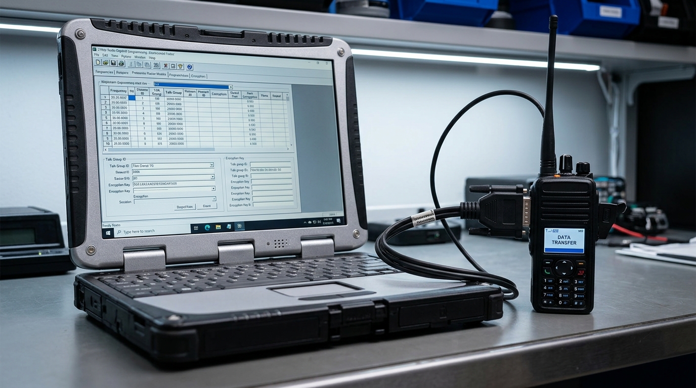
Essential Hardware Connections and Driver Setup
To successfully establish communication between a PC and a transceiver, 2-way radio programming software requires a precise hardware and digital interface layer. The system relies on three interconnected components:
-
The Programming Cable: A specialized data link customized to match the unique accessory port of the radio model. Unlike standard consumer cables, professional radio programming cables feature inline hardware chipsets (such as FTDI or Prolific) that convert the computer’s USB signals into universal asynchronous receiver-transmitter (UART) or serial data lines.
-
USB-to-Serial Device Drivers: The host computer’s operating system requires matching, up-to-date device drivers to correctly interpret the cable’s inline chipset. Without these drivers, the PC cannot map the physical connection.
-
Virtual COM Ports: Once recognized by the operating system, the cable is assigned a specific virtual COM port (e.g., COM3). The user must manually select this exact active identifier within the programming software settings to open a clear path for data transfer.
Channel Mapping and Frequency Parameters
The primary function of 2-way radio programming software involves building the channel database by mapping exact frequencies to specific memory slots. Within the software’s parameter tables, technicians enter distinct transmit ($Tx$) and receive ($Rx$) frequencies down to the individual hertz.
This precise entry is crucial when configuring fleet communications for repeater systems, where the radio must transmit on one frequency and receive on another with a strict megahertz offset. Additionally, the software dictates the channel bandwidth. Technicians use this setting to toggle between legacy wideband configurations (25 kHz) and strict, legally mandated narrowband allocations (12.5 kHz) to ensure the radio operates within its designated spectral boundaries without bleeding into adjacent channels.
Logical Fleet Organization via Zones
As commercial radio networks scale, managing a massive list of individual frequencies becomes overwhelming for the end user. 2-way radio programming software resolves this operational hurdle by organizing channels into logical folders called Zones.
A zone allows an administrator to partition a radio’s memory into distinct, easily navigable groups based on job function, department, or geography. For example, a resort fleet can be programmed with “Zone 1: Security,” “Zone 2: Housekeeping,” and “Zone 3: Engineering.” The user can then switch between these zones using the radio’s keypad or menu system, filtering out irrelevant chatter and streamlining daily workplace communications.
Analog Squelch Codes and Digital Color Filtering
To eliminate interference from other businesses sharing the same or adjacent radio frequencies, programming software provides advanced squelch filtering. In traditional analog systems, this is managed via Continuous Tone-Coded Squelch Systems (CTCSS/PL) or Digital Coded Squelch (DCS/DPL). The software configures the radio to encode an inaudible, low-frequency sub-tone onto the voice transmission; receiving radios programmed with the matching code will unmute their speakers only when that specific tone is detected.
In Digital Mobile Radio (DMR) setups, the software manages this filtering through Color Codes (numbered 0 through 15). The color code functions as a strict digital handshake. If a radio picks up a transmission on its assigned frequency but detects a mismatched color code, the internal microprocessor discards the voice packets entirely, maintaining a quiet environment for the user.
Digital Mobile Radio (DMR) Talkgroup Configuration
When deploying digital radio platforms, two-way radio programming software introduces complex configuration layers that do not exist in analog systems. For DMR fleets, the software is used to build a robust digital architecture featuring:
-
Unique Radio IDs: The software assigns an exclusive digital identification number to every physical radio in the network, allowing individual tracking, private calling, and remote monitoring.
-
Talkgroups: Technicians build digital talkgroups, which act as virtual channels. Multiple teams can share a single physical frequency, but they will only hear transmissions directed to their specific talkgroup ID.
-
Time Slots: DMR technology splits a single 12.5 kHz channel into two independent paths via Time Division Multiple Access (TDMA). The programming software dictates whether a channel communicates on Time Slot 1 or Time Slot 2, effectively doubling the network’s capacity without requiring extra frequency licenses.
Interface Customization and Physical Button Mapping
A significant benefit of utilizing professional 2-way radio programming software is the ability to customize the physical layout of the radio’s buttons to match specific operational roles. Modern professional radios feature several unassigned buttons, usually found on the side of the housing below the Push-to-Talk (PTT) switch or on the top crown next to the antenna.
Through the software’s interface configuration matrix, administrators can assign distinct functions to both “Short Press” and “Long Press” actions for each button. A short press on a side button can be programmed to instantly toggle the channel scan list on or off, while a long press on that same button can be locked down to switch between high and low transmission power levels, helping preserve battery life during long shifts.
Automated Life-Safety and Telemetry Settings
For industrial environments, manufacturing plants, and isolated job sites, two-way radio programming software serves as the deployment mechanism for automated life-safety protocols. Technicians can use the software to activate and fine-tune critical safety features, including:
-
Lone Worker Mode: This parameter initiates an internal countdown timer within the radio firmware. If the user fails to interact with the device (such as pressing the PTT or turning a knob) within a pre-configured window (e.g., 45 minutes), the radio emits an audible warning. If the user does not respond to the alert, the software instructs the radio to automatically transmit a distress beacon to dispatch.
-
Man Down Sensing: This activates an internal gyroscopic tilt or motion sensor. The programming software allows technicians to define a specific angle (e.g., horizontal tilt beyond $45^\circ$) and a immobility timeout. If the radio remains in that position for too long, indicating the operator has fallen or is incapacitated. It immediately triggers an emergency broadcast.
-
Emergency Routing: This maps the exact destination channel and priority level for incoming distress signals, ensuring life-safety alerts override standard voice traffic across the entire network.
Conclusion
Manually typing frequencies, talkgroups, and button settings for dozens or hundreds of individual radios is incredibly time-consuming and prone to human error. 2-way radio programming software completely optimizes this process through cloning workflows.
A technician builds a single, highly detailed “golden template” codeplug containing the standardized configurations for a specific radio model. Once this template file is verified and saved to the computer’s hard drive, the cloning process begins. The technician connects successive radios of the exact same model type and writes. The master file directly to their memories in rapid succession. This ensures absolute fleet uniformity, simplifies future troubleshooting, and reduces deployment timelines from days to minutes.
FAQ,s
CPS stands for Customer Programming Software. This is the official proprietary term used by major manufacturers like Motorola Solutions, Kenwood, Icom, and Hytera. Describe the applications used to configure their radios.
Can I use one brand of software to program a different brand of radio?
No. 2-way radio programming software is highly proprietary and brand-specific. A Motorola radio requires Motorola CPS. Kenwood radio requires Kenwood KPG software. An Icom radio requires Icom CS software. They are completely incompatible across different brands.
What is a radio codeplug?
A codeplug is the actual configuration file generated and read by the programming software. It contains the complete operating parameter data such as channel lists, frequencies, zones, privacy codes. And button mapping layouts—for a specific radio model.
What is the difference between reading and writing a radio?
“Reading” a radio extracts the active configuration data. Out of the transceiver’s physical memory chip and opens it as a viewable. Editable codeplug file on your computer screen. “Writing” a radio uploads the open configuration file from your programming software into the radio, completely overwriting its previous settings.
Why does my software throw a “Model Mismatch” error?
This protective error occurs when the codeplug file currently. Open in your software does not perfectly match the physical hardware profile. Frequency band, or firmware version of the radio connected to the PC. The software blocks the write function to prevent damaging the radio’s memory.
Is it legal to program any frequency I want into my radio software?
No. It is illegal to program and transmit on frequencies without explicit authorization or a valid spectrum. License from your regional communications authority (such as the FCC in the United States). Programming unlicensed frequencies can interfere with critical public safety and emergency networks.
What happens if the cable is disconnected while writing data to a radio?
Interrupting a write process can corrupt the radio’s internal memory chips. Resulting in an unresponsive unit—a state commonly known as “bricking.” If this occurs, you will typically need to use an integrated firmware recovery. Tool within the programming software to completely flash and rebuild the device’s operating files.